White Paper: Frequency Optimised Cables for Cellular Networks
Synopsis
Optimising cable length to frequency wavelength in connected cables used in cellular telephone communications can preserve signal power and mitigate PIM. Fabricating cables whose ‘electrical’ length is directly divisible by its ‘desired’ frequency or signal wavelength maintains signal power and harmonises phase thereby reducing the impact of reflections, non-linearities and Inter-Modulations caused by phase displacement. The ability to optimise phase angle at connection points throughout the signal channel would maintain VSWR and promote signal linearity.
Introduction
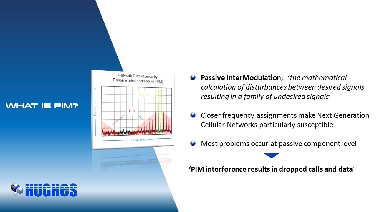
Passive Intermodulation (PIM) - the distortion generated in communication channels which results in mixing of products from a desired generating signal causes transmit frequencies to mix into the system’s receive band, it is a widely recognised source of problematic interference. The contribution of passive system products such as cables and connectors and in particular jumper cables is by no means trivial, in fact it cannot be understated. But the ability to predict PIM from these sources could allow engineers to account for PIM in the system design phase, potentially mitigating PIM to near noise floor level.
This paper describes a step in that direction, it focusses on the PIM produced by displaced signal Phase throughout the passive channel and describes a method of calculation and mitigation.
Phase Displacement
Phase displacement - relative displacement between two corresponding points of simultaneous signal waveform cycles having the same frequency (figure 1) damages transmission. It causes signal reflections which diminishes Standing Wave Ratio (SWR) in high-frequency networks and results in signal Inter-Modulation.
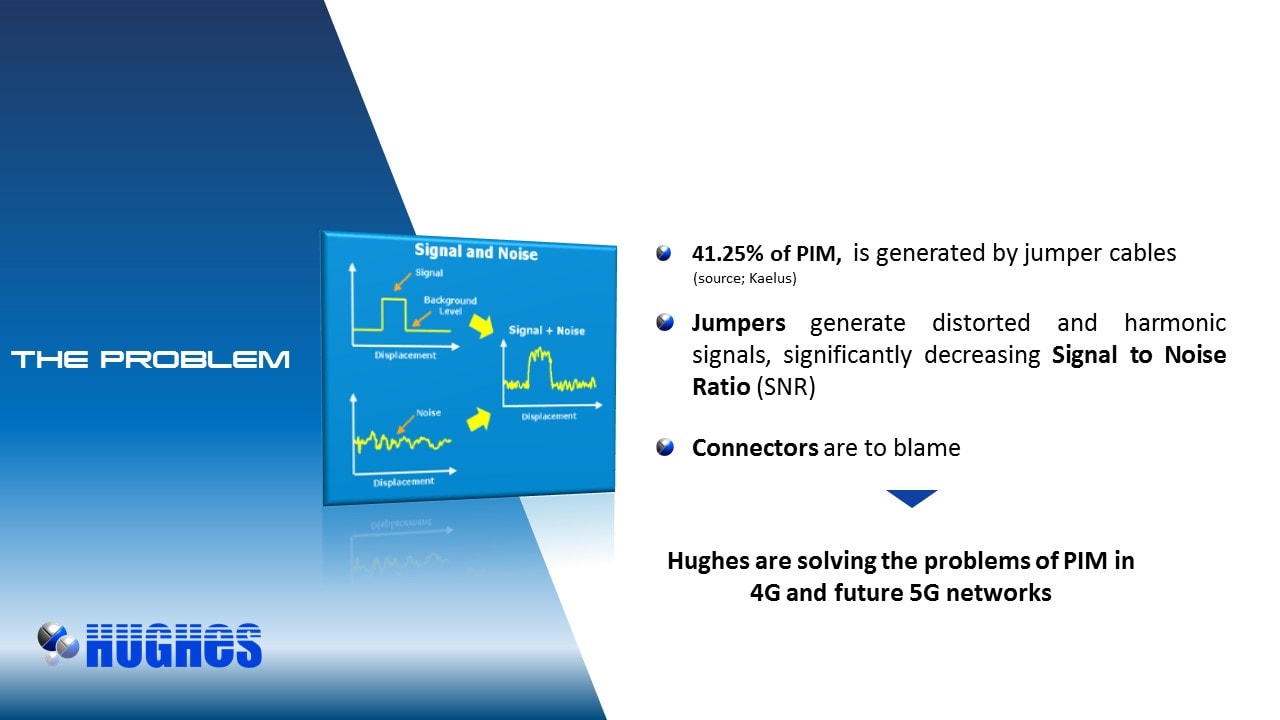
Each reflection causes an equivalent loss of amplitude to SWR of the desired transmitted signal, IM becomes more acute as a result of the increasing difference in power between desired transmitted and actual received signals. The more impoverished received signal strength becomes the more vulnerable it is to IM, in these situations some PIM distortion levels as low as -150dBc are reported to become problematic, especially where transmit and receive bands are closely spaced.
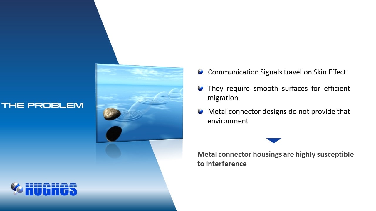
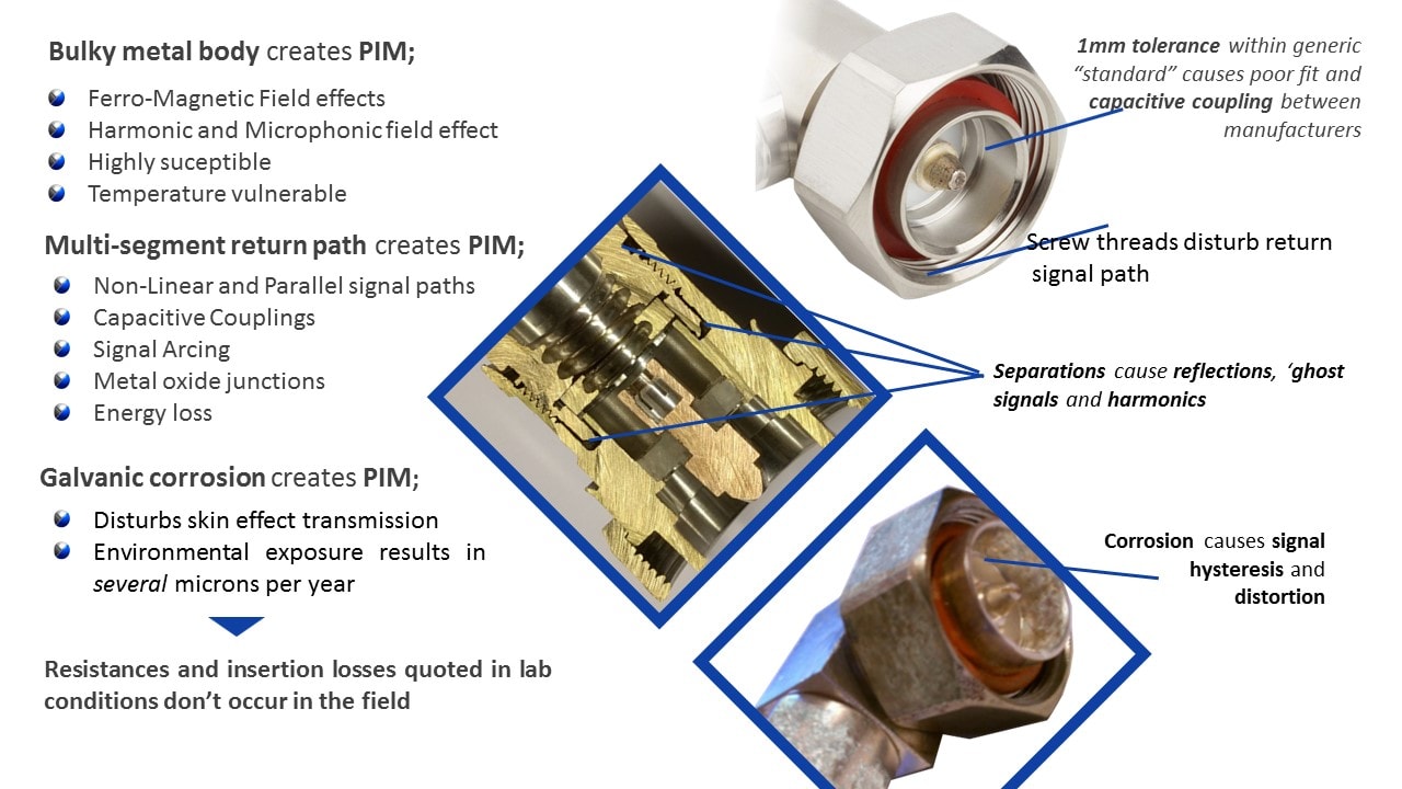
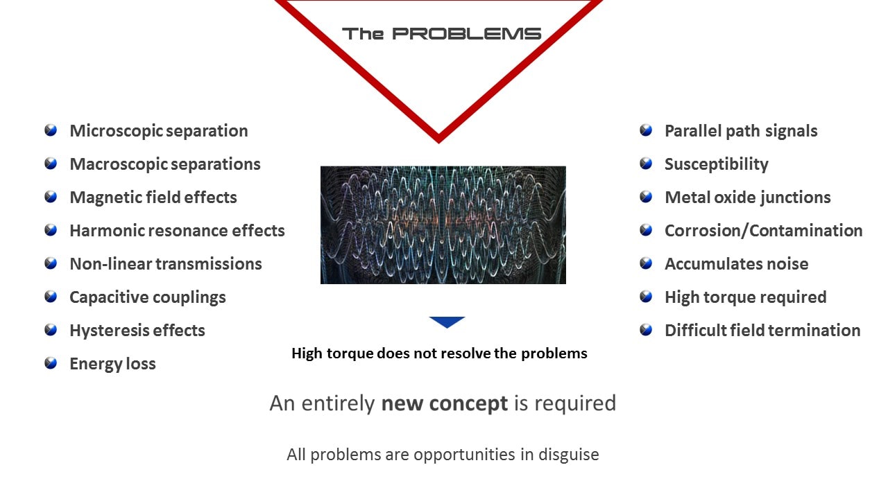
The significant non-linear properties of metal coaxial connectors frequently make them the dominant contributors to poor signal transit. The multiple obstacles to efficient transmission through these types of connector’s results in multiple signal distortions, non-linearity’s and signal phase displacement [1]. It may be argued that whatever the physical cause of a signal distortion and its pernicious effects on a transmission, the signal phase displacement product of the problem is the catalyst for the lion’s share of non-linearity.
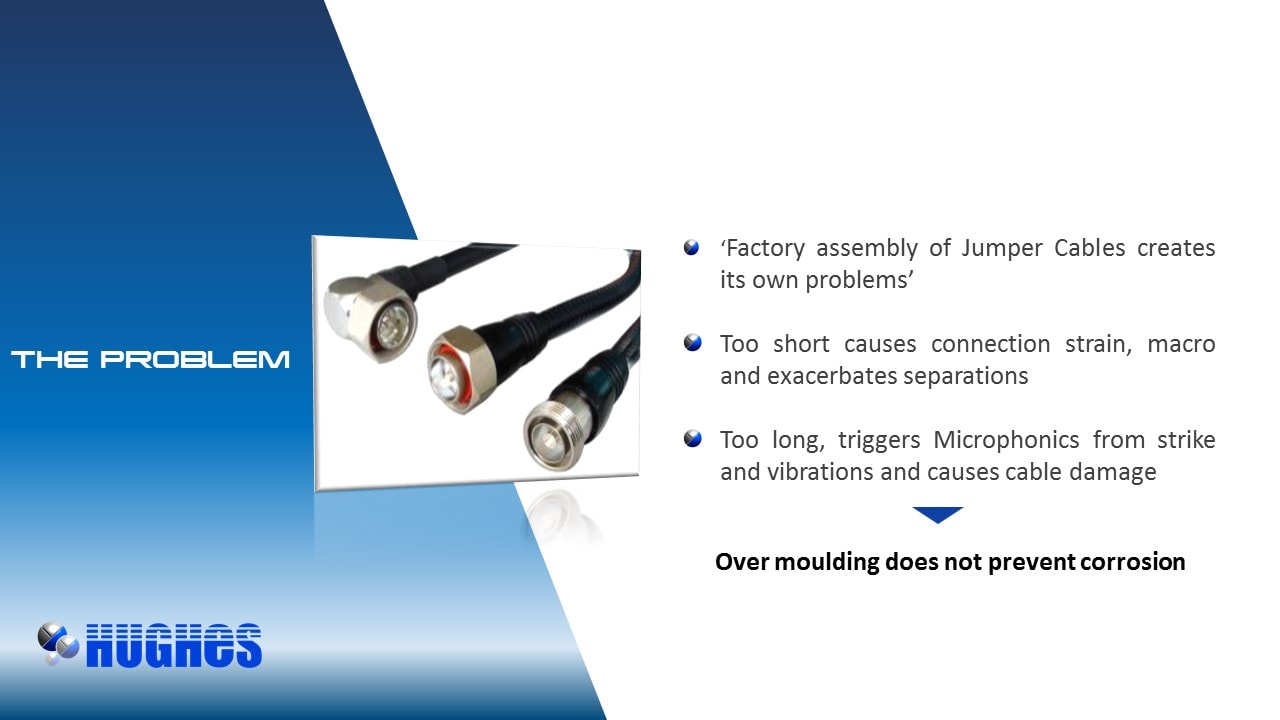
Cables themselves generate very little PIM but Jumper cables incorporate two coaxial connectors in short order, it follows that the sum of phase disruptions is usually greater in Jumper cables than any other part of the cable channel so it is quite understandable why jumper cables in particular are blamed for generating so much 3rd order PIM.
Signal phase angle though is rarely seriously considered in passive channel design. In fact neither the connectors nor the cables themselves are designed for phase congruency with the carrier frequency [2] so in respect of PIM, it seems that we reap what we sow.
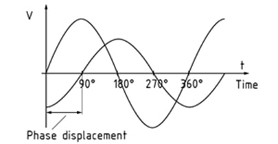
Figure 1 - Phase displacement (relative displacement between two corresponding points of simultaneous cycles having the same frequency) triggers signal reflections resulting in impoverished VSWR and PIM.
Influencing Phase
PIM testers provide reasonable evidence of system PIM but cannot be relied on as a PIM prediction tool.
In explaining the difference between the actual and predicted data when measuring IM in cable assemblies Kaelus notes [3] that its model assumes its (jumper cable) DUT to be lossless and rationalises the discrepancy thus; because there is a vector combination of IM sources with differing phases it is expected that the (actual) reflected IM response is a factor of frequency and assembly length (sic).
If correct, the assertion suggests frequency wavelength and cable length are not unconnected and it follows that adjustment of either parameter may modulate or ‘shift’ phase angle, by so doing assisting in maintaining phase, reducing reflections and PIM palliation.
A previous paper from the author [1] also alludes to phase angle, or rather its preservation, along with papers [2], [5] and [6], playing an important role in PIM.
This paper focusses on phase shifting in jumper cables and shows, whilst they (jumper cables) undoubtedly make a major contribution to PIM, the ability to calculate their overall phase offset and adjust cable length to harmonise near and far end phase could help conserve signal linearity, power and mitigate PIM.
Wavelength Vs Cable length
Each cycle (Hz) of a frequency has a unique (wave) length (figure 2), multiples of which combine to make the unique frequency waveform or Sine Wave. The distance between the top and bottom of the waveform measures the amplitude or power of the wave.
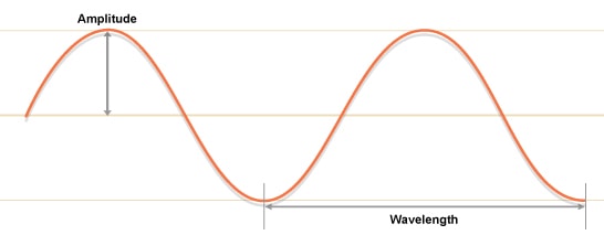
Figure 2 – Signal amplitude and wavelength
Source signals ‘ride’ on the waveform assuming the wave length, amplitude and band width of the frequency, the higher the frequency the shorter the wave length (Figure 3) and more vulnerable it is to phase (and other types of) disruption.
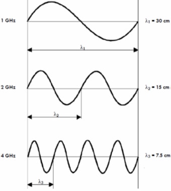
Figure 3 - Wavelength λ in cm at different frequencies
To maintain phase, any position at an instant in time on a waveform cycle must be maintained. If phase can be maintained throughout the channel i.e the phase position at the near end of the channel is the same as the phase position at the far end of the channel the signal will be seen in phase or linear and there will be fewer reflections from at least those points.
On the other hand phase disruption of desired signals will result in reflected signals and consequentially loss of desired signal power (amplitude). The performance of the channel diminishes commensurately as the power of the desired signals diminishes and the magnitude of undesired (reflected) signals grows. The more dominant the power of undesired signals and the more submissive the desired signals the more acute the problem of IM.
The term phase has also been used relating to two consecutive frequency cycles (Figure 4). If they are equidistant at all points at the same time, they too are said to be in phase. Conversely, if two consecutive signals with the same frequency are not in exact alignment at the same time, they are said to be out of phase. [4]
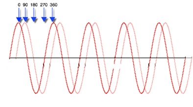
Figure 4 - 2 wave forms 90 degree out of phase
When an antenna receives multiple cycles that are in phase (zero degree phase displacement) their amplitude is aggregated, which results in a received signal of much greater signal strength, potentially as much as twice its origin amplitude.
If two consecutive signals are 180 degrees out of phase (the top of one cycle is in exact alignment with the low of the second cycle), they cancel each other out and the received power is nil. Phase displacement also has a cumulative effect, depending on the amount of displacement signal strength may be either increased or decreased accordingly (Figures 5&6). It follows that to improve our cellular communications infrastructure we need to begin to take every opportunity possible to preserve and use phase to our advantage.
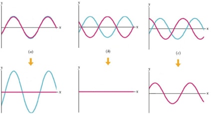
Figure 5 – Results of mixing signals in different phases. (a) – Constructive - both signals are in phase and the result signal is a sum of both signal amplitudes. (b) – Destructive – signals are 180⁰ out of phase and the resulting signal is completely cancelled out. (c) – Intermediate – signals out of phase – resulting signal is a sum of both waves
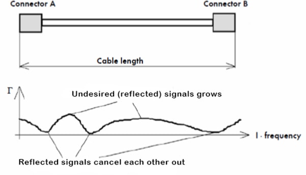
Figure 6 - With two discontinuities, shows how reflected signals can combine and aggregate or cancel each other out at different frequencies. The magnitude of the total reflected signals depends on the distance (wavelengths) between the discontinuities and signal frequency
Length is important
Standard length cables - 1 metre, 2 metre etc. are invariably at odds with frequency wavelength which causes phase shift and its consequences.
The evidence seems to suggest that adjustment of cable length to harmonise with frequency phase should improve phase displacement thereby improving VSWR and IM3 PIM. In other words if cable length (L), including the length of connectors equals a multiple (m) of the carrier frequency wavelength (λ), phase could theoretically be maintained, signal strength enhanced and accumulated phase displacement cancelled.
L= λ·m (1)
Alternatively half λ/2 or quarter λ/4 wavelength can be considered for the in phase length calculation in equation (1)
Let's consider standard 2m jumper length at different carrier frequencies.
At 910MHz the half wavelength (λ/2) for typical jumper cable is equal to 0.13365m. Using equation (1) and multiplier m=15 we get cable length of 2.00m. Based on that it can be concluded that 2m jumper lead should perform well at 900MHz.
At 800MHz the half wavelength (λ/2) is equal to 0.375m. Using equation (1) and multiplier m=15 we get cable length of 1.97m. That result shows that the phase of proposed 2m jumper will not be maintained as the optimal length at that frequency is 3cm shorter.
Test Methods
PIM is predicted using fundamental circuit and transmission line theory.
The general methodology is explained to verify accuracy of our measurement system.
- Specific third-order PIM levels are measured for some common jumper cable lengths (DUT’s)
- An experiment using the techniques outlined herein is used to predict the total IM distortion of an RF network involving several different types of coaxial cable lengths as a function of power.
Experiments
PIM response of typical 2m jumper length was tested at different carrier frequencies within 900MHz band.
By using equation (1) it was predicted that the 2m lead should perform the best at frequencies of 910 and 940MHz.
The results of the tests are presented on Figure 8. A trend can be seen with cable performing better at some frequencies. That trend matches the prediction that was made using equation (1).
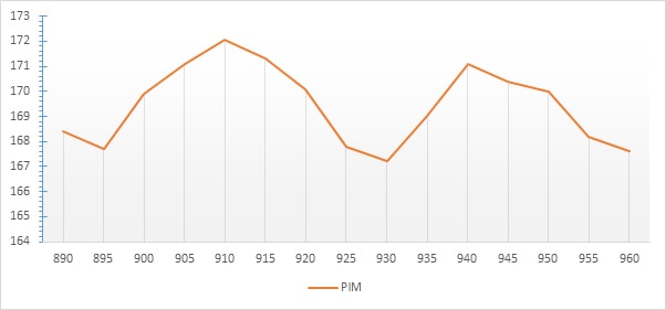
Figure 8 – PIM vs frequency test results for a typical 2m jumper
Complications
Clearly enough improvement in PIM in some frequencies is shown to demonstrate that the closer the cable gets to frequency phase optimisation the better the PIM becomes. But the formula from equation (1) does not provide the adequate predictive tool to allow us to control the optimisation of length and phase. It does open the door however to the possibility that more accurate profiling of overall cable losses can put the opportunity of full linearity or near full linearity tantalising close. Calculating the phase/PIM/length relationship to achieve that goal is however non-trivial.
Squaring the circle
To reconcile these differences it is necessary to profile the phase and PIM parameters of the DUT then use an abstract algebraic equation to find the unit of length per degree of phase needed to reconcile phase at near and far end. A compound of the unit of length per degree and the no. of degrees of phase displacement provides us with the length of cable adjustment that needs to be added or subtracted to an industry standard length in order match the phase at the near and far end and create more linear looking transmissions.
To correctly calculate the phase, knowledge of electrical length of the cable is required. Electrical length (wavelength λ) is influenced by the dielectric material used in the cable. Figure 9 shows relationship between the materials' dielectric constant and propagation velocity of the signal (and in turn wavelength).
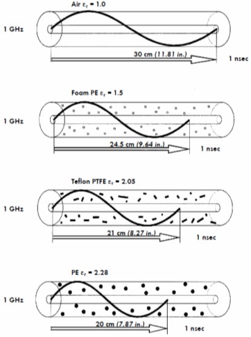
Figure 9 –Influence of the dielectric material on the wavelength
From that we know that the physical and ‘electrical’ length of the cable can differ based on the cable construction and materials used. This electrical length governs a cables velocity of propagation, to accurately calculate required cable length in order to optimise phase for onward transmission the cables' propagation velocity therefore needs to be taken into consideration.
ν=c/√ε (2)
Where:
ν – velocity of the wave
c – speed of light in vacuum ~300000km/s
ε – dielectric constant of the cable' material
λ=ν/f (3)
Where:
λ – wavelength in m
ν – velocity of the wave
f – frequency
φ=(360*L)/λ (4)
Where:
ϕ – Phase shift in degrees
λ – wavelength in m
L- electrical cable length (for quarter wave use L*4)
Using the above equations
At 910MHz quarter wavelength (λ/4) is equal to 0.06676425m. Using equation (1) and a multiplier m of 15 the cable length is equal to 1.0015m. That means that 1m jumper lead will be optimal length for 910MHz applications.
Knowing cable length and propagation velocity (in this case 81%), phase shift (cable length in degrees for quarter wavelength) can be calculated using equation (4).
φ=(360degrees*1m)/0.06676425m=5392.10 degrees
Cables available on the market have length tolerance. Let's assume that the actual cable length is 98cm rather than 1m. In that case phase shift will be:
φ=(360degrees*0.98m)/0.06676425m=5284.26 degrees
Phase difference between the two cable lengths Δϕ is: Δφ=107.84 degrees
The difference of 2cm in length causes a phase shift of 107.84 degrees.
By taking this result and using equation (5) as a prediction method described in [2] we can estimate PIM values at specific intermodulation frequencies and cable lengths.
V_im^-=∑_(n=1)^N▒〖V_n exp(j2βl_n)〗 (5)
More experiments
Jumper cable with a length of 1.1m was assembled and tested for PIM response at 910MHz. Next the same cable had been shortened by 1cm retested and results saved.
The process was repeated until the length of 0.8m was reached.
The results of the tests are presented in Figure 10 below. The graph shows a PIM response to change in length. As can be seen there are some lengths at which the PIM response is better. Notably 0.8m, 0.87m, 0.93m, 1m and 1.07m.
Those lengths align with the calculations for quarter wavelength of 910MHz for cable type used in the tests.
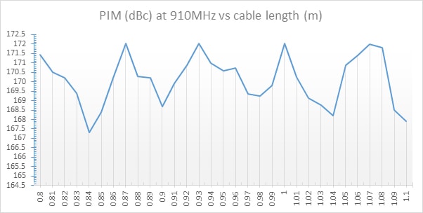
Figure 10 – PIM test result at 910MHz vs. cable length
Conclusion
Deploying cables standardised by arbitrary metre denominated lengths which are generally phase incongruent displaces phase and designs signal degradation and PIM into the system. Distorting cable geometry by bending and looping excess cable to try to accommodate standard lengths exacerbates the problem.
Conversely deploying cable lengths optimised to signal carrier frequency wavelengths reduces phase displacement, improves Linearity and preserves amplitude delivered.
Whereas phase harmonisation at connection points can do nothing to abate signal losses before the crucial transition point, it can influence PIM results by up to 5dB (see figure 10) on a jumper cable and make the difference between a system pass or fail.
Using the techniques described it should also be possible to calculate residual channel phase and improve its linearity by adjusting its overall length. Jumper Leads provide a simple tool for doing that.
REFERENCES
[1] Hughes Electronics
[2] J. Henrie, A. Christianson, W. J. Chappell, "Prediction of passive intermodulation from coaxial connectors in microwave networks", Birck and NCN Publications, 2008
[3] Rick Hartman, "Measuring the Passive Intermodulation Performance of RF Cable Assemblies", Kaelus, 2011
[4] The CWNA definition of Phase v106
[5] J. Henrie, A. Christianson, W. J. Chappell, "Cancellation of Passive Intermodulation Distortion in Microwave Networks", 2008
[6] tuanjie li, kai zhang and jie jiang, " Passive intermodulation model and experimental verification of cascaded microwave devices", 2017